Mechanical Shock Resistance of a Vehicle Power Distribution Unit
Environmental Qualification according to MIL-STD-810H – Method 516.8 (Shock / Mechanical Shock)
Background
Military ground vehicles are subjected to high-intensity mechanical shocks during operation. These shock loads may occur due to:
- weapon firing and recoil forces
- abrupt impacts while driving off-road
- collision with obstacles
- transportation by aircraft, rail, or ship
- nearby explosions or blast events
Critical subsystems installed in such vehicles must be capable of withstanding these mechanical shock loads without failure. One important component is the vehicle power distribution unit (PDU), responsible for distributing electrical power to multiple subsystems such as:
- turret electronics
- communication systems
- navigation systems
- sensor modules
- auxiliary control units
Mechanical shock can cause severe stresses on electronic and mechanical structures, potentially leading to:
- cracking of circuit boards
- detachment of heavy components
- loosening of connectors
- deformation of mounting interfaces
Therefore, functional components intended for installation in military vehicles must be tested for shock resistance according to MIL-STD-810H Method 516.8 (Mechanical Shock).
Test Objective
The objective of the test was to verify that a vehicle power distribution unit can withstand shock loads representative of those encountered during military vehicle operation and transportation.
The test evaluated:
- structural integrity of the enclosure
- robustness of internal electronics
- connector stability
- functionality during and after shock exposure
Device Under Test (DUT)
Equipment:
Vehicle power distribution unit (PDU).
Application:
Electrical power distribution for onboard vehicle subsystems.
Construction:
The unit was installed on a representative vehicle mounting structure simulating its real installation inside the vehicle hull.
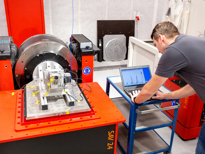
Test Setup
Testing was conducted using a mechanical shock test system, capable of generating controlled shock pulses representative of real operational loads.
The DUT was mounted on the shock table using its standard mounting configuration. Shock pulses were applied along the three principal axes of the component.
Accelerometers were attached to the DUT and mounting fixture to verify shock levels during testing.
Test Conditions
Testing followed the procedures defined in MIL-STD-810H Method 516.8.
A functional shock test profile representative of military vehicle conditions was applied.
The DUT remained powered during selected shock pulses to evaluate operational stability.
Monitoring and Inspection
During the test, the performance of the power distribution unit was monitored to detect any anomalies.
Monitoring included:
- electrical output monitoring
- connector stability checks
- internal power rail stability
- accelerometer measurements
After completion of the shock test sequence, the DUT was subjected to a comprehensive inspection.
Post-Test Inspection
Detailed inspection was conducted to identify any structural or functional degradation.
Inspection procedures included:
- visual inspection of the housing
- examination of PCB assemblies
- inspection of connectors and mounting hardware
- full electrical functionality test
Test Results
The power distribution unit remained fully functional throughout the shock test.
Engineering Assessment
The ability of the unit to withstand mechanical shock loads was attributed to several key design features:
- rigid aluminum enclosure providing structural protection
- reinforced PCB mounting points
- shock-resistant connector locking systems
- optimized internal mass distribution to reduce stress concentrations
These design measures significantly reduced the mechanical stresses transmitted to sensitive electronic components.
Conclusion
The vehicle power distribution unit successfully passed environmental qualification testing according to MIL-STD-810H Method 516.8 (Mechanical Shock).
The component maintained full structural integrity and operational functionality under shock loads representative of military vehicle operation.
This confirms that the system is suitable for installation in high-mobility military ground vehicles exposed to severe mechanical shocks.
Marketing Summary
Engineered to withstand extreme mechanical shocks.
Testing according to MIL-STD-810H Mechanical Shock demonstrates that critical vehicle electronics maintain operational reliability even when exposed to high-impact shock events.
Through robust mechanical design, reinforced internal structures, and shock-resistant mounting systems, manufacturers can ensure long-term reliability of mission-critical vehicle electronics in demanding operational environments.