
We also offer the following tests, among others:
Vibration tests are used to qualitatively check the strength of components (short-term vibration tests) or for life tests.
Structural weak points in components by means of time acceleration can therefore be detected.
We perform transport simulations with vibration profiles (road transport, rail transport or air transport) as well as the generation of short-term mechanical shocks, which can occur, for example, when driving over stones in the terrain or when lifting and dropping a transport item. In the automotive field, vibration, which is driven sinusoidally or with a stochastic noise profile, is usually driven with high and / or low temperatures superimposed. Here, tests of the most extreme type with the superimposition of sine over sine are also used in order to be able to drive high amplitudes through superimposed waveforms and thus shorten the test time.
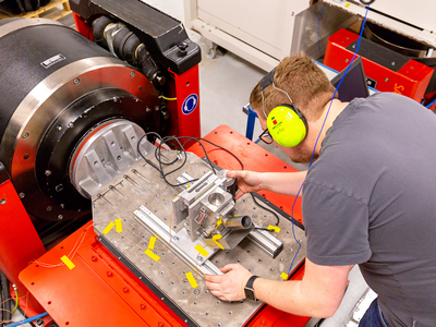
Vibration and Shock Test
Normen
- DIN EN 2591-403
- DIN EN 60068-2-6
- DIN EN 60068-2-64
- DIN EN 60721-3-2
- DIN EN 61373
- DIN SPEC 79009
- MIL-STD-810H Method 514→ Case Study
- RTCA DO-160G Section 7→ Case Study
- automotive standards (e.g. VW and BMW standards)


Explanation of the vibration test(click to open)
Vibration tests are used to check the stability and anchorage of a wide variety of products from a wide range of industries and applications. They serve both to increase product comfort - by helping to eliminate unpleasant noise such as squeaking, for example - and to extend product service life, such as fundamental product safety and thus the safety of the user. They simulate as realistically as possible all the conditions under which the respective products are used. This allows the stability of structures and the reliability of connections between components to be checked.
The test objects are vibrated with the aid of a shaker. The vibrator usually consists of a platform on which the object is fixed.
The vibrations can be transmitted to the object in two ways, either as "random" ones, where different frequencies are involved at the same time, or as "sinusoidal" ones, which show a continuous, frequency-wise progression (increasing/decreasing curve). Accordingly, a distinction is made between "random vibration tests" and "sinusoidal vibration tests".
"Random vibration tests" usually depict the actual conditions of use of the products somewhat more realistically. A product often has more than one resonant frequency. Random tests with several simultaneous frequencies can quickly provide analyses that allow statements about service life and susceptibility to repair.
In the "sine vibration test", a frequency spectrum is run through. The so-called sine sweeps can be used to determine the frequencies at which the product shows the strongest response behavior.
Both test methods can also be combined to form "mixed mode vibration tests". Here the random oscillations are merged with resonance dwell times of a sine test.
Exemplary areas of application for vibration tests
Automotive
The vibrations caused by the road surface are significant for the automobile (and the occupants). In the tests, they are usually simulated by random vibration profiles that include smooth road surfaces as well as potholes, thresholds or even the behavior during braking.Opening and closing doors and hoods should also be included.
Aeronautics and astronautics
Aircraft must meet particularly stringent requirements because they can be subjected to particularly severe conditions and the safety and possibly the lives of their occupants depend on their reliability. Vibrations occur primarily during takeoff and landing as well as during weather-related turbulence.
Even stronger vibration stresses are encountered in space travel. Especially during the launch phase of a rocket, the load on systems and components can be as high as 20 G for about two minutes. But also during re-entry and eventual landing of the objects the vibration loads are enormously high.
In both cases, mixed-mode test procedures are appropriate.
Vibration testing of consumer goods
Consumer goods are also frequently exposed to vibrations in everyday life, which can be simulated by tests in order to increase the resistance and service life of the products. Kitchen appliances and furniture are just one example. In addition, many products have to undergo vibration tests to obtain certifications (e.g. CE). And last but not least, the transport routes - from the manufacturer to the dealer and finally to the consumer - contain many sources of vibration exposure. Packaging tests are necessary to ensure safety here.
Military vibration testing
Especially for military equipment, which is often exposed to high vibration stress, demanding tests have to be performed, for which our laboratory is specifically equipped. Here, according to military standards (see below), we are almost always talking about mixed-mode test executions.
Standards
Aeronautics and astronauticsRTCA-DO-160 is one of the most widely used test standards here.
Military sectorHere, the most commonly requested is MIL-STD-810, as well as MIL-STD 202 next to it. Part 1 of Standard-810 requires testing at a vibration frequency of 25 Hz and above. This standard also covers the effects of multiple events that may occur simultaneously. These include temperature, humidity and altitude in combination with vibrations.